| CPC F04D 29/646 (2013.01) [F04D 25/088 (2013.01); F16M 13/027 (2013.01)] | 8 Claims |

|
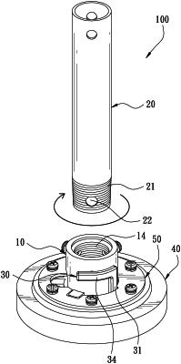
1. A down rod installation structure for a ceiling fan, comprising:
a coupling seat, having a coupling portion and an annular portion, the coupling portion having an opening, the coupling portion further having a coupling space therein, the opening communicating with the coupling space, the coupling portion having an internal thread on a peripheral wall of the coupling space, a peripheral side of the coupling portion having a perforation;
a down rod, having a threaded portion corresponding to the internal thread of the coupling portion, the threaded portion of the down rod being in the coupling space and being threadedly connected to the internal thread of the coupling portion, the threaded portion of the down rod having an aperture corresponding to the perforation of the coupling portion;
an elastic member, including an elastic portion and an abutment portion connected to the elastic portion, the elastic portion being disposed outside the coupling portion, the elastic portion having a fixed end and a free end connected to the fixed end, the fixed end of the elastic portion being fixed to the coupling seat, the abutment portion being connected to the free end of the elastic portion, the abutment portion corresponding to the perforation of the coupling seat and the aperture of the down rod, one side of the abutment portion, opposite to the elastic portion, having an inclined portion corresponding to the threaded portion of the down rod, the inclined portion having a first end and a second end, the inclined portion being inclined from the first end to the second end, the first end being disposed adjacent to the elastic portion and the opening, the second end being disposed away from the elastic portion and the opening;
wherein when the elastic portion is in a normal state, the free end of the elastic portion is in a normal statue position adjacent to an outer wall of the coupling portion and the perforation, and the abutment portion is located in the coupling space and the perforation; when the abutment portion is pushed by the down rod to elastically displace the abutment portion and the free end of the elastic portion to be in a stressed state, the free end of the elastic portion is in a stressed state position away from the outer wall of the coupling portion and the perforation, and the abutment portion is moved away from the coupling space, the free end of the elastic portion is displaceable between the normal state position and the stressed state position; when the down rod is coupled to the coupling portion, the free end of the elastic portion returns to the normal state position, and the abutment portion is engaged in the perforation of the coupling portion and the aperture of the down rod.
|