| CPC F04B 33/00 (2013.01) [F04B 25/005 (2013.01); F04B 25/02 (2013.01); F04B 27/005 (2013.01); F04B 39/123 (2013.01); F04B 49/08 (2013.01)] | 9 Claims |

|
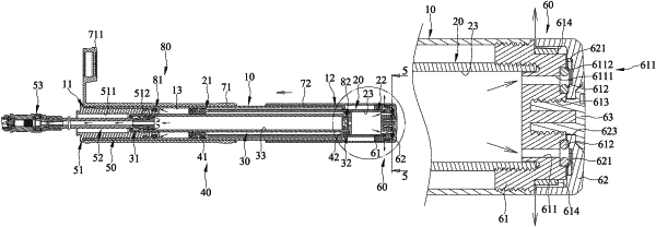
1. A variable-pressure air pump comprising:
a first cylinder defining a first chamber;
a second cylinder movably connected with the first cylinder and defining a second chamber fluidly communicable with the outside of the variable-pressure air pump selectively;
a plunger having a first end inserted in first chamber and a second end inserted in the second chamber and defining a one-way flow passage fluidly connecting with the first and the second chambers;
a piston device configured to compress air in the first and the second chambers; and
a discharge device including a connecting member and a switch movably connected with one another, wherein the connecting member defines at least one discharge hole fluidly connecting with the second chamber, wherein the switch has at least one flow guide portion fluidly connecting with the outside of the variable-pressure air pump and at least one blocking portion which is adapted to block the at least one discharge hole, wherein the switch is movable between a first position in which the at least one flow guide portion is adjacent and opens to the at least one discharge hole and a second position in which the at least one blocking portion is adjacent to and blocks the at least one discharge hole, wherein the discharge device is disposed at an end opposite to an end of a head assembly of the variable-pressure air pump, wherein the switch is fastened to the connecting member by a fastener, wherein the connecting member and the switch respectively defines a first hole and a second hole and the fastener is inserted through the second hole and engaged with the first hole, wherein the switch is rotatably connected with the connecting member, wherein the connecting member has two limits configured to obstruct movement of the switch, wherein the switch in the first position thereof is obstructed by one of the two limits, wherein the switch in the second position thereof is obstructed by the other of the two limits, and wherein the switch defines two grooves and the two limits are movably engaged in the two grooves respectively and move therein upon moving the switch with respect to the connecting member.
|