| CPC F04B 23/04 (2013.01) [F04B 15/02 (2013.01); F04B 17/03 (2013.01)] | 20 Claims |

|
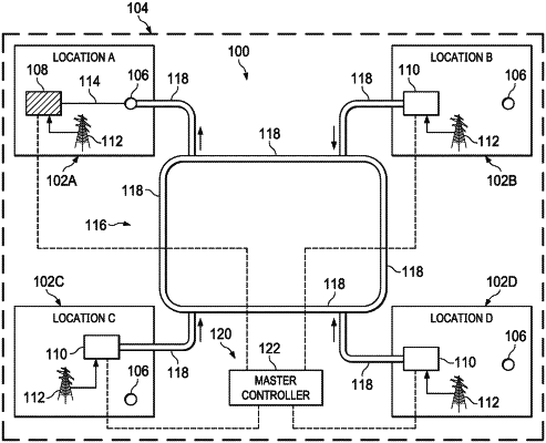
1. A system, comprising:
a first clean pump unit disposed at a first location;
a first grid power supply that provides power to the first clean pump unit;
a slurry pump unit disposed at a second location, wherein the slurry pump unit is fluidly coupled to a high pressure manifold at the second location, wherein the high pressure manifold is fluidly coupled to a well bore at the second location, wherein the first location and the second location are 100 yards to 2 miles apart;
a second grid power supply that provides power to the slurry pump unit;
a first flow path fluidly connected to the first clean pump unit at the first location and configured to fluidly connect the first clean pump unit to the high pressure manifold at the second location or to a wellhead above the wellbore at the second location;
a second clean pump unit disposed at a third location, wherein the third location is 100 yards to 2 miles apart from the first location and from the second location;
a third grid power supply that provides power to the second clean pump unit;
a third clean pump unit disposed at a fourth location, wherein the fourth location is 100 yards to 2 miles apart from the first location, from the second location, and from the third location;
a fourth grid power supply that provides power to the third clean pump unit;
a piping network configured to provide bidirectional flow, wherein the first flow path is connected to the piping network;
a second flow path fluidly connected to the piping network and configured to fluidly connect the piping network to the high pressure manifold or to the wellhead above the wellbore at the second location;
a third flow path fluidly connected to the second clean pump unit at the third location and configured to fluidly connect the second clean pump unit to the piping network; and
a fourth flow path fluidly connected to the third clean pump unit at the fourth location and configured to fluidly connect the third clean pump unit to the piping network; and
a master controller communicatively coupled to the first clean pump unit at the first location and to the slurry pump unit at the second location, wherein the master controller is configured to control an operation of the first clean pump unit and the slurry pump unit.
|