| CPC F01D 5/26 (2013.01) [F01D 5/10 (2013.01); F01D 5/3046 (2013.01); F01D 5/3084 (2013.01); F05D 2240/11 (2013.01); F05D 2300/6033 (2013.01)] | 18 Claims |

|
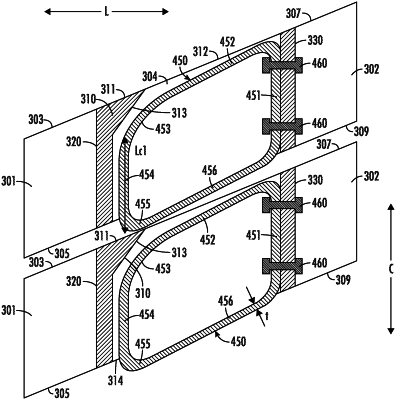
1. An airfoil assembly for a turbine engine defining an axial direction, a radial direction, and a circumferential direction, the airfoil assembly comprising:
a first airfoil defining a first end along the radial direction;
a first hub disposed on the first end of the first airfoil and comprising a first extension member extending at least partially in the radial direction;
a second airfoil adjacent to the first airfoil, the second airfoil defining a first end along the radial direction;
a second hub disposed on the first end of the second airfoil and comprising a second extension member extending at least partially in the radial direction; and
a circumferential bias assembly operable with the first extension member and the second extension member for exerting a circumferential force on at least one of the first extension member or the second extension member,
wherein the circumferential bias assembly is a first shroud assembly,
wherein the first shroud assembly comprises a first spring member coupled to the first extension member, positioned adjacent to the first extension member, or both,
wherein the first extension member is part of a first pair of extension members spaced apart in the axial direction to define a first space therebetween, and
wherein the first shroud assembly is disposed in the first space between the first pair of extension members.
|