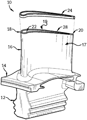
| CPC F01D 5/187 (2013.01) [B23K 1/0018 (2013.01); F01D 11/122 (2013.01); B23P 15/04 (2013.01); F05D 2220/32 (2013.01); F05D 2230/10 (2013.01); F05D 2230/237 (2013.01); F05D 2260/20 (2013.01)] | 20 Claims |

|
1. A method of forming a gas turbine engine component, the method comprising:
providing an airfoil extending radially from a base to a blade tip, wherein the airfoil comprises:
a pressure sidewall and a suction sidewall each extending between a leading edge and a trailing edge opposite the leading edge; and
an internal cooling circuit extending from the base to the blade tip;
forming a presintered preform comprising:
a first squealer tip rail;
a second squealer tip rail adjacent to the first squealer tip rail; and
a squealer tip cap extending between the first and second squealer tip rails;
disposing, before brazing the presintered preform to the blade tip, a filler material between the first and second squealer tip rails; and
brazing the presintered preform to the blade tip, wherein the blade tip, the first and second squealer tip rails, and the squealer tip cap define an internal squealer tip cooling channel, and wherein the blade tip defines a supply aperture that fluidly connects the internal cooling circuit and the internal squealer tip cooling channel.
|