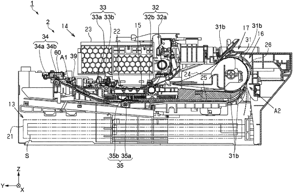
| CPC B41J 13/009 (2013.01) [B41J 2/01 (2013.01); B41J 3/60 (2013.01); B41J 11/04 (2013.01); B41J 13/0036 (2013.01); B41J 13/0045 (2013.01); B41J 13/025 (2013.01)] | 8 Claims |

|
1. A recording device, comprising:
a recording unit configured to perform recording on a recording medium;
a first transport path in which the recording medium is transported in a first direction during recording by the recording unit;
a second transport path that is coupled to the first transport path in a position downstream of the recording unit in the first direction, and in which the recording medium, on which recording was performed by the recording unit, is transported in a second direction different from the first direction in a path different from the first transport path;
a first discharge roller pair disposed in a position upstream in the first direction from a coupling position of the first transport path with the second transport path, and configured to sandwich the recording medium on which recording was performed by the recording unit, and transport the recording medium in the first direction;
a second discharge roller pair disposed in the coupling position or disposed downstream of the coupling position in the first direction, configured to sandwich the recording medium, and apply a transport force in the first direction to the recording medium in the first transport path and a transport force in the second direction to the recording medium in the second transport path, and the second discharge roller pair being formed of a second discharge driving roller and a second discharge driven roller;
a first driving motor configured to drive the first discharge driving roller;
a second driving motor configured to drive the second discharge driving roller; and
a movement mechanism configured to move the second discharge roller pair to a sandwiching state where the second discharge driving roller and the second discharge driven roller sandwich the recording medium, and to a separated state where the second discharge driving roller and the second discharge driven roller are separated, wherein
the movement mechanism includes:
an eccentric cam,
a slide cam configured to interlock with the eccentric cam, and
a surface of the slide cam slidable moves in contact with a rotary shaft of the second discharge driven roller, and thus the second discharge driven roller moves to the sandwiching state and the separated state with respect to the second discharge driving roller, and
the second discharge roller pair is in the separated state in a part of a period in which the recording medium is transported.
|