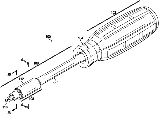
| CPC B25B 23/0035 (2013.01) [B25B 15/02 (2013.01); B25G 1/085 (2013.01)] | 2 Claims |

|
1. A locking mechanism for locking a bit at a forward end of a tubular shaft, the locking mechanism comprising:
a passageway defined within the tubular shaft for facilitating travel of the selected bit between a rearward end of the tubular shaft and a forward end of the tubular shaft opposing the forward end;
at least one locking finger formed longitudinally in the tubular shaft and cantilevered from the tubular shaft at a rearward end of the at least one locking finger for facilitating radial spring action at a forward end of the at least one locking finger;
at least one locked detent and at least one unlocked detent formed in the at least one locking finger and longitudinally spaced from each other, the at least one locked detent being rearward of the at least one unlocked detent;
a track extending between the at least one locked detent and the at least one unlocked detent;
a locking sleeve slidably positioned on the shaft proximate the at least one locking finger; and
at least one roller ball mounted in the locking sleeve portion for engaging one of the at least one locked detent and the at least one unlocked detent, the at least one roller ball being rollable along the track between the at least one locked detent and the at least one unlocked detent.
|