| CPC B03C 1/284 (2013.01) [B03C 1/0332 (2013.01); B03C 1/286 (2013.01); B03C 2201/20 (2013.01)] | 7 Claims |

|
1. A temperature-controlled tramp metal separation assembly comprising:
a housing including a front wall, a rear wall, a first side wall, a second side wall, a first inner plate and a second inner plate, the front and rear walls combining with the first and second side walls to define a receiving space within the housing, the first inner plate and the second inner plate being respectively disposed between the first side wall and the second side wall to divide the receiving space into a first discharging area, a second discharging area and a feeding area;
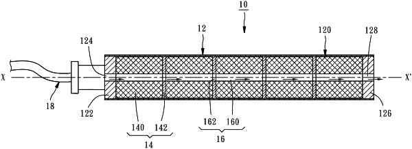
a plurality of core rods, each of the core rods made of non-magnetic materials and including a first longitudinal axis, a chamber, a first closed end with at least an air inlet, a closed second end with at least an air outlet;
a plurality of magnetic sets, each magnetic set including a plurality of magnetic members and a plurality of spacers made of a material having a high magnetic permeability or a high saturation magnetization and respectively disposed between two adjacent magnetic members;
the chamber of the core rod having a first part, a second part, a third part and an air path, the first part forming a first non-magnetic section and a first portion of the air path, the second part forming a magnetic section by nesting one of the magnetic sets therein along the longitudinal axis in a way that a second portion of the air path is formed, and the third part forming a second non-magnetic section and a third portion of the air path;
the first inner plate having a plurality of first bores and the second inner plate having a plurality of second bores;
each of the core rods passing through each of the first bores of the first inner plate, each of the second bores of the second inner plate and securing respectively each of ends thereof on the front and rear walls in a way that the first and second non-magnetic sections correspond respectively to the first and second discharging areas and the magnetic section corresponds to the feeding area;
a plurality of sleeve tubes, each of the sleeve tubes made of non-magnetic materials and including a first portion, a second portion, a longitudinal length less than the longitudinal length of the core rod and an axial hole with an inner diameter larger than the outer diameter of the core rod so that the sleeve tube can be sleeved outside the core rod in a way that the sleeve tube passes through the first bore of the first inner plate and the second bore of the second inner plate to be moveable to and fro along the longitudinal axis of the core rod and between a first position, wherein the first portion corresponds to the magnetic section to capture tramp metals of raw materials and the second portion corresponds to the second non-magnetic section to discharge tramp metals captured thereon, and a second position, wherein the first portion corresponds to the first non-magnetic section to discharge tramp metals captured thereon, and the second portion corresponds to the magnetic section to capture tramp metals of raw materials;
a cooling air transmitting unit coupled with each of the core rods to introduce an external cooling air flow from the air inlet, and then discharged from the air outlet via the air path;
a first driving plate fixedly connected to a first end of each of the sleeve tubes and disposed in the first discharging area, the first driving plate having a plurality of third bores for being passed through by the core rods;
a second driving plate fixedly connected to a second end of each of the sleeve tubes and disposed in the second discharging area, the second driving plate also having a plurality of fourth bores for being passed through by the core rods;
a pair of guiding rods disposed respectively on each of the side walls of the housing, each of the guiding rods having a second longitudinal axis parallel to the first longitudinal axis of the core rod;
the first driving plate further having a pair of first guiding openings passed through by each of the guiding rods, the second driving plate further having a pair of second guiding openings passed through by each of the guiding rods; and
a linear actuator connected with the first or the second driving plates for actuating the sleeve tubes to move back and forth along the core rods between the first position and the second position.
|