| CPC H02M 3/155 (2013.01) [H02M 1/0058 (2021.05); H02M 3/158 (2013.01); H02M 7/53871 (2013.01); H02M 1/42 (2013.01); H02M 7/4815 (2021.05)] | 5 Claims |

|
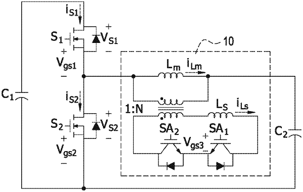
1. A soft-switching power converter, comprising:
a main switch being a controllable switch,
an energy-releasing switch coupled to the main switch, and
an inductive coupled unit coupled to the main switch and the energy-releasing switch, the inductive coupled unit comprising:
a main inductor,
an auxiliary inductor wound on the main inductor, and
an auxiliary switch unit coupled to the auxiliary inductor to form a closed loop,
wherein the main switch and the energy-releasing switch are alternately turned on and turned off, and the auxiliary switch unit is controlled to start turning on before the main switch is turned on so as to provide at least one current path;
wherein the inductive coupled unit further comprises a circular magnet on which the main inductor is wound, the auxiliary inductor is wound on the circular magnet, the main inductor has a first couple end coupled to the main switch and a second couple end coupled to an output capacitor of the soft-switching power converter, and the first couple end is disposed adjacent to the second couple end on the circular magnet;
wherein the auxiliary inductor has a third couple end coupled to one end of the auxiliary switch unit, and a fourth coupled end coupled to another end of the auxiliary switch unit, and the third couple end is disposed opposite to the fourth coupled end on the circular magnet;
wherein a coil turns ratio between the main inductor and the auxiliary inductor is 1:N, wherein Nis a natural number; and
wherein when a leakage inductor current of the auxiliary inductor increases to be greater than 1/N of a magnetizing inductor current of the main inductor, the auxiliary switch unit starts turning on before the energy-releasing switch is turned off so that the main switch operates in a zero-voltage switching mode.
|