| CPC H02J 50/005 (2020.01) [H01F 27/2823 (2013.01); H02J 50/12 (2016.02); H02J 50/60 (2016.02); H04B 5/0037 (2013.01); H02J 50/80 (2016.02); H02J 50/90 (2016.02)] | 20 Claims |

|
1. A power transmitter for wireless power transfer at an operating frequency selected from a range of about 87 kilohertz (kHz) to about 205 kHz, the power transmitter comprising:
an interface surface;
a control and communications unit;
an inverter circuit configured to receive input power and convert the input power to a power signal;
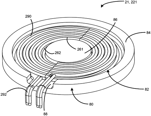
a coil configured to transmit the power signal to a power receiver, the coil formed of wound Litz wire and including at least one layer, the coil defining, at least, a coil top face;
a ferrite shielding comprising a magnetic core, a magnetic backing, and a magnetic ring having a magnetic ring top face, wherein the magnetic core is centrally positioned on the magnetic backing and the magnetic ring is positioned around an outer edge of the magnetic backing, wherein the magnetic core, the magnetic backing, and the magnetic ring define a cavity in the ferrite shielding, wherein the coil is positioned within the cavity and the cavity is configured such that the ferrite shielding substantially surrounds all but the coil top face, wherein the coil top face is positioned above the magnetic ring top face, and wherein a gap is defined between an outermost turn of the coil and the magnetic ring; and
at least one magnet configured as a ring, the at least one magnet comprises a magnet top face, wherein the at least one magnet substantially surrounds the outermost turn of the coil, and wherein the at least one magnet is configured to attract at least one receiver magnet when the power receiver is proximate to the interface surface associated with the power transmitter,
wherein the magnet top face is separated from the interface surface by a first separation distance and the coil top face is separated from the interface surface by a second separation distance, and wherein the first separation distance is less than the second separation distance.
|