| CPC G09G 3/3406 (2013.01) [G09G 3/3685 (2013.01); G09G 2320/0257 (2013.01)] | 17 Claims |

|
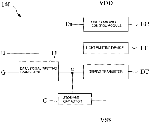
1. A backlight driving circuit, for driving a backlight module, wherein the backlight driving circuit comprises:
a light emitting device connected in series to a light emitting loop formed by a first power signal and a second power signal;
a driving transistor, wherein a source and a drain of the driving transistor are connected in series to the light emitting loop, a gate of the driving transistor is electrically connected to a first node, and the driving transistor is configured to control a current flowing through the light emitting loop;
a data signal writing transistor, wherein a source of the data signal writing transistor is connected to a data signal, a drain of the data signal writing transistor is electrically connected to the first node, and a gate of the data signal writing transistor is connected to a scan signal;
a storage capacitor, wherein a first terminal of the storage capacitor is electrically connected to the first node, and a second terminal of the storage capacitor is connected to the second power signal; and
a light emitting control module, wherein the light emitting control module is connected to an enable signal and connected in series to the light emitting loop, and the light emitting control module is configured to control the light emitting loop to be turned on or off based on the enable signal;
wherein a driving timing of the backlight driving circuit comprises a scan period, a display period, and a black insertion period; and
during the scan period, the data signal writing transistor is turned on, and the light emitting the control module is turned off; during the black insertion period, the scan signal is at a low level, and the signal writing transistor is turned off; the enable signal is at a low level, the light emitting control module is turned off, and the backlight module is turned off; and the scan period and the black insertion period consist of a black frame insertion of a backlight.
|