| CPC G06V 10/28 (2022.01) [G06T 5/002 (2013.01); G06T 5/40 (2013.01); G06T 7/194 (2017.01); G06V 10/60 (2022.01); H04N 5/272 (2013.01); G06T 2207/10081 (2013.01)] | 5 Claims |

|
1. A binarization method for computed tomography (CT) sectional image of fiber package containing artifacts, comprising:
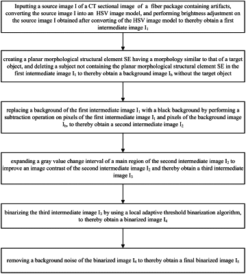
step 1, inputting a source image I of a CT sectional image of fiber package containing artifacts, converting the source image I into a hue-saturation-value (HSV) image model, and performing brightness adjustment on the source image I obtained after converting of the HSV image model to thereby obtain a first intermediate image I1;
wherein the step 1 specifically comprises:
step 1.1, defining a brightness value of each pixel of the source image I as V, and V∈ [0, 255];
step 1.2, drawing a brightness distribution histogram of the source image I to thereby obtain a range [a, b] of a brightness value Vgx of a fiber region of the fiber package, a maximum value M of the brightness value Vgx, and a range [a′, b′] of a brightness value V range of a region of the fiber region most affected by the artifacts; and
step 1.3, performing, based on a composite tangent function and according to a formula 1.1, nonlinear brightness adjustment on each pixel of the source image I obtained after converting of the HSV image model, to thereby obtain the first intermediate image I1:
V′=V−A tan(BV+φ) (formula 1.1),
where V′ represents a lightness value after nonlinear brightness adjustment, V represents the brightness value before nonlinear brightness adjustment, A represents a range control coefficient, B represents an adjustment coefficient of lightness control range, and φ represents an origin-point control coefficient;
wherein in the step 1.3,
the composite tangent function is a part of a tangent function in a range of [−3 T/8, 3 T/8], T represents a period of the tangent function;
the range control coefficient A satisfies a formula 1.2:
 the adjustment coefficient of lightness control range B satisfies a formula 1.3:
 the origin-point control coefficient co satisfies a formula 1.4:
 step 2, creating a planar morphological structural element SE having a morphology similar to that of a target object, and deleting a subject not containing the planar morphological structural element SE in the first intermediate image I1 to thereby obtain a background image Ib without the target object;
step 3, replacing a background of the first intermediate image I1 with a black background by performing a subtraction operation on pixels of the first intermediate image I1 and pixels of the background image Ib, to thereby obtain a second intermediate image I2, wherein the second intermediate image I2 is obtained by a formula 3.1 expressed as follows:
I2=I1−Ib (formula 3.1);
step 4, expanding a gray value change interval of a main region of the second intermediate image I2 to improve an image contrast of the second intermediate image I2 and thereby obtain a third intermediate image I3;
step 5, binarizing the third intermediate image I3 by using a local adaptive threshold binarization algorithm, to thereby obtain a binarized image I4;
wherein the step 5 specifically comprises:
step 5.1, when different neighborhood radii are selected, calculating a relative difference Δ between a connected domain number nr and an actual section number N of an optical fiber core in a same region according to a formula 5.1, and adaptively obtaining an optimal neighborhood radius r required by the local adaptive threshold binarization algorithm for achieving an optimal binarization effect:
 step 5.2, calculating a gray mean m(x, y) and a standard variance s(x, y) in a neighborhood of r×r of each pixel of the third intermediate image I3 according to a formula 5.2 and a formula 5.3, respectively:
  where g(i, j) represents a gray value of each pixel in the neighborhood of r×r; and
step 5.3, calculating a binarization threshold T(x, y) of each pixel in the neighborhood of r×r according to a formula 5.4, and obtaining a binarized image I4:
T(x,y)=m(x,y)+z·s(x,y) (formula 5.4),
where z represents a denoising coefficient, which is preset by experience; and
step 6, removing a background noise of the binarized image I4 to thereby obtain a final binarized image I5.
|