| CPC G01R 27/08 (2013.01) [G01R 15/04 (2013.01)] | 3 Claims |

|
1. A method for achieving terminal-pair definition of four-terminal-pair (4TP) impedance, comprising:
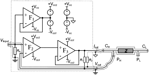
connecting a current output terminal of a two-stage follower to a high current terminal of impedance through a coaxial line, and connecting a voltage output terminal of the two-stage follower to a high voltage terminal of the impedance through the coaxial line, to thereby make a current of the high voltage terminal of the impedance be zero, and a core wire current and an outer wire current of the high current terminal equal and reverse;
wherein the two-stage follower comprises: a first follower F1, a second follower F2 and a third follower F3; and the first follower F1 is a first-stage follower, the second follower F2 and the third follower F3 are combined to be a second-stage follower;
wherein a power supply ±Vcc of the first-stage follower and a power supply ±Vcc2 of the second-stage follower are independent of each other, and an output terminal of the first follower F1 is connected to a center point of the power supply ±Vcc2 of the second-stage follower;
wherein the method further comprises:
connecting an output terminal of the second follower F2 to a non-inverting input terminal of the third follower F3;
connecting a core wire of the current output terminal Iout of the two-stage follower to a core wire of the voltage output terminal Vout of the two-stage follower through a first resistance R1, and connecting an outer wire of the current output terminal Iout to an outer wire of the voltage output terminal Vout through a second resistance R2;
connecting an input terminal VInput of the two-stage follower to a non-inverting input terminal of the first follower F1 and a non-inverting input terminal of the second follower F2, individually, and connecting the input terminal VInput of the two-stage follower to an outer wire of the input terminal VInput through an input resistance Rin, that is, connecting the input terminal VInput of the two-stage follower to reference ground through the input resistance Rin;
connecting an output terminal of the third follower F3 to the current output terminal Iout of the two-stage follower, and connecting an inverting input terminal of the second follower F2 to the voltage output terminal Vout of the two-stage follower;
connecting the outer wire of the current output terminal Iout of the two-stage follower to a center point of the power supply ±Vcc of the first-stage follower; and
connecting the outer wire of the voltage output terminal Vout of the two-stage follower to the outer wire of the input terminal VInput.
|