| CPC G01N 1/08 (2013.01) [G01N 33/24 (2013.01)] | 20 Claims |

|
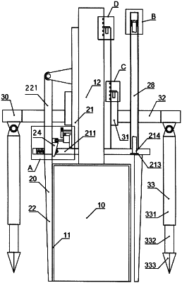
1. A sampling device for evaluating ecological risk of soil in a high geological background area, comprising an impact sampling mechanism (10), a soil layer stripping mechanism (20) and an auxiliary support frame (30), wherein
the impact sampling mechanism (10) comprises a sampling hopper (11) with a downward opening, a connecting sliding rod (12) is fixedly arranged on the top of the sampling hopper (11), and an upper end of the connecting sliding rod (12) is connected with a hollow impact rod (13);
the impact rod (13) is internally provided with an impact hammer (131) which is motor-driven to reciprocate within the impact rod (13) along an axis of the impact rod (13) through a crank-link mechanism;
the soil layer stripping mechanism (20) comprises a stripping sliding cylinder (21) in sliding fit with the connecting sliding rod (12), a support disc (211) is fixedly arranged on the stripping sliding cylinder (21), a plurality of stripping plates (22) are connected to a lower side edge of the support disc (211) in a sliding fit mode, and the stripping plates (22) are motor-driven and can move along a radial direction of the support disc (211);
the stripping plates (22) are combined into an annular structure surrounding an outer side of the sampling hopper (11), and dimensions of the annular structure combined by the stripping plates (22) along an axial direction of the sampling hopper (11) are larger than axial dimensions of the sampling hopper (11);
the auxiliary support frame (30) comprises a stable support cylinder (31) connected to the outer side of the stripping sliding cylinder (21) in a sliding fit mode, a stable support plate (32) is fixedly arranged on the stable support cylinder (31), and a lower side of the stable support plate (32) is connected with a plurality of telescopic stable legs (33);
a plurality of sector ring accommodating grooves (213) are formed in a lower side of the support disc (211), and a plurality of telescopic through holes (214) running from top to bottom are formed in the support disc (211) and located at the sector ring accommodating grooves (213);
a telescopic control column (28) is fixedly arranged on the top of the support disc (211) at one of the telescopic through holes (214), the telescopic control column (28) is of a hollow structure, the telescopic control column (28) is internally provided with a telescopic rod (281) in a sliding fit mode, a rotating fit hole (282) running from top to bottom is formed in the telescopic rod (281), and the rotating fit hole (282) is internally provided with a rotating rod (283) in a running fit mode;
a low end of the rotating rod (283) extends through one of the telescopic through holes (214), and a cutting plate (284) is fixedly arranged at a lower end of the rotating rod (283);
a first motor (285) is fixedly arranged in the top of the telescopic control column (28), the first motor (285) drives the telescopic rod (281) to move along an axis of the telescopic control column (28) through a screw lead mechanism, a second motor (286) is fixedly arranged on the top of the telescopic rod (281), and the second motor (286) is used for driving the rotating rod (283) to rotate in the rotating fit hole (282); and
a driving fit plate (287) is fixedly arranged on the telescopic rod (281), a threaded hole (288) running from top to bottom is formed in the driving fit plate (287), a threaded rod (289) is fixedly arranged on an output shaft of the first motor (285), and the threaded rod (289) is in threaded running fit in the threaded hole (288).
|