| CPC G01D 5/20 (2013.01) [H01F 38/14 (2013.01)] | 9 Claims |

|
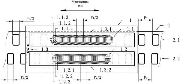
1. A hybrid positioning electromagnetic induction displacement sensor, the sensor comprising a transceiver board (1) and an excitation board (2) that may move relative to each other along a measuring path, wherein
the transceiver board (1) is arranged with a measurement circuit and at least one transmitter winding extending along the measuring path, each transmitter winding respectively encircles a first pitch three-phase receiver winding and a second pitch three-phase receiver winding by using two approximately closed rectangular coils in the same direction in series, each three-phase receiver winding comprises three phase windings with the same structure and a phase difference of 120° in sequence, both the transmitter winding and the three-phase receiver winding being connected to the measurement circuit; the measurement circuit comprises a central control unit, an interface unit, and a measurement unit, the central control unit comprising a microcontroller (13), and the interface unit comprising a key input circuit, a liquid crystal drive circuit, a measurement interface circuit, and a power source conversion circuit that are connected to the microcontroller (13); and
the excitation board (2) is arranged with at least two rows of excitation coils that extend along the measuring path, wherein the number of the at least two rows of excitation coils arranged on the excitation board is equal to that of the three-phase receiver windings on the transceiver board (1), each row of excitation coil and a corresponding three-phase receiver winding on the transceiver board (1) have the same pitch and coincided center lines respectively, and a length of each of the excitation coils and a length of a three-phase receivers winding along the measuring path is half of a respective pitch;
wherein the measurement unit comprises an oscillator, a frequency dividing circuit (3), a signal generator consisting of a driving and sampling pulse forming circuit (4) and a line voltage scanning control signal generator (5), an analog signal processing circuit consisting of an analog switch group (6), sample-and-hold capacitors (C1, C2), a differential amplifier (7), a low-pass filter (8), and a zero-crossing detector (9), a phase quantization circuit consisting of a synchronous delay circuit, an up counter (10), random access memories (11, 12) and a synchronous capture circuit, and transmitter winding drive power tubes (T1, T2), two sets of analog signal processing circuits, random access memories, and synchronous capture circuits being respectively arranged to form two parallel processing channels; and
the oscillator provides an input clock for the driving and sampling pulse forming circuit (4), the line voltage scanning control signal generator (5), the low-pass filter (8), the synchronous capture circuit and the up counter (10) directly or through the frequency dividing circuit (3): in addition to connecting to the analog switch group (6), the driving and sampling pulse forming circuit (4) is connected to the transmitter winding drive power tubes (T1, T2) directly or through a multi-way switch (S14), and the line voltage scanning control signal generator (5) is separately connected to the analog switch group (6) and the synchronous delay circuit: the analog switch group (6), the differential amplifier (7), the low-pass filter (8), the zero-crossing detector (9), the synchronous capture circuit are connected in sequence, and the sample-and-hold capacitors (C1, C2) are connected between an input end of the differential amplifier (7) and the analog signal ground: the synchronous delay circuit is separately connected to the synchronous capture circuit and the up counter (10), and the up counter (10) and the synchronous capture circuit are respectively connected to the random access memories (11, 12): each transmitter winding is connected to a power source through respective driving power tube (T1 or T2), and each three-phase receiver winding is connected to the analog signal ground in a star-shaped (Y) joint and neutral point.
|