| CPC F28F 3/048 (2013.01) [F28D 1/0316 (2013.01); F28D 9/0043 (2013.01); F28D 2021/0028 (2013.01); H05K 7/20009 (2013.01)] | 5 Claims |

|
1. A low pressure drop automotive liquid-cooling heat dissipation plate, comprising:
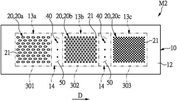
a heat dissipation plate body having a first heat dissipation surface and a second heat dissipation surface that are opposite to each other, wherein the first heat dissipation surface is in contact with a first traction inverter power component set, a second traction inverter power component set, and a third traction inverter power component set, and the first, second, and third traction inverter power component sets together form an inverter power module for generating a three-phase alternating current for driving an automotive motor, wherein the second heat dissipation surface is in contact with a cooling fluid;
a first fin set located in a first heat dissipation region, wherein the first heat dissipation region is defined by a first projection area formed by projecting the first traction inverter power component set on the second heat dissipation surface;
a second fin set located in a second heat dissipation region, wherein the second heat dissipation region is defined by a second projection area formed by projecting the second traction inverter power component set on the second heat dissipation surface; and
a third fin set located in a third heat dissipation region, wherein the third heat dissipation region is defined by a third projection area formed by projecting the third traction inverter power component set on the second heat dissipation surface;
wherein a surface area formed by the first fin set located in the first heat dissipation region and in contact with the cooling fluid is less than a surface area formed by the second fin set located in the second heat dissipation region and in contact with the cooling fluid, and the surface area formed by the first fin set located in the first heat dissipation region and in contact with the cooling fluid is less than a surface area formed by the third fin set located in the third heat dissipation region and in contact with the cooling fluid;
wherein any two adjacent ones of the first, second, and third heat dissipation regions have a low density heat dissipation region formed therebetween, a low density fin set is formed on the second heat dissipation surface and located in the low density heat dissipation region, and a surface area formed by the low density fin set located in the low density heat dissipation region and in contact with the cooling fluid is less than 50% of the surface area formed by the first fin set located in the first heat dissipation region and in contact with the cooling fluid;
wherein a contour of each of fins of the first fin set that is located in the first heat dissipation region is drop-shaped, and a contour of each of fins of the second fin set and the third fin set that are respectively located in the second heat dissipation region and the third heat dissipation region is round-shaped;
wherein a centroid-to-centroid distance between any two adjacent ones of the fins of the first fin set that is located in the first heat dissipation region ranges from 1.3 mm to 1.5 mm, and a centroid-to-centroid distance between any two adjacent ones of the fins of the third fin set that is located in the third heat dissipation region ranges from 1.0 mm to 1.2 mm.
|