| CPC F26B 21/08 (2013.01) [F25B 30/02 (2013.01); F25B 40/06 (2013.01); F25B 41/30 (2021.01)] | 3 Claims |

|
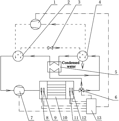
1. A closed variable-frequency heat pump drying device with a heat regenerator, comprising a variable-frequency compressor (1), a condenser (2), a throttling valve (3), an evaporator (4), a heat regenerator (5), a three-way valve (6), a variable-frequency fan (7), an air inlet temperature sensor (8), an air inlet humidity sensor (9), a drying bin (10), an air outlet temperature sensor (11), an air outlet humidity sensor (12) and a controller (13), wherein
the air inlet temperature sensor (8) and the air inlet humidity sensor (9) both are installed at an inlet of the drying bin (10) to sense air inlet temperature T1 and air inlet humidity φ1 at the inlet of the drying bin (10); the air outlet temperature sensor (11) and the air outlet humidity sensor (12) both are installed at an outlet of the drying bin (10) to sense the air outlet temperature T2 and the air outlet humidity φ2 at the outlet of the drying bin (10);
the variable-frequency compressor (1), the condenser (2), the throttling valve (3) and the evaporator (4) are connected in series in sequence to form a heat pump system; an outlet of the heat regenerator (5) faces one side of the condenser (2), and another outlet of the heat regenerator (5) faces one side of the evaporator (4); an inlet of the heat regenerator (5) faces the other side of the evaporator (4), and another inlet of the heat regenerator (5) is communicated with an outlet of the three-way valve (6); another outlet of the three-way valve (6) faces the other side of the evaporator (4), and an inlet of the three-way valve (6) is communicated with the outlet of the drying bin (10); an inlet of the variable-frequency fan (7) faces the other side of the condenser (2), and an outlet of the variable-frequency fan (7) is communicated with the inlet of the drying bin (10); and condensed water of the evaporator (4) is directly discharged outside through a pipeline; and
the controller (13) is electrically connected with the variable-frequency compressor (1), the three-way valve (6), the variable-frequency fan (7), the air inlet temperature sensor (8), the air inlet humidity sensor (9), the air outlet temperature sensor (11) and the air outlet humidity sensor (12) respectively.
|