| CPC F16H 63/3425 (2013.01) [B60T 1/005 (2013.01); F16D 63/006 (2013.01); F16H 63/304 (2013.01); F16H 63/3433 (2013.01); F16H 63/3466 (2013.01); F16H 63/3491 (2013.01); F16H 2063/3056 (2013.01)] | 13 Claims |

|
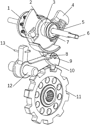
1. An electronic parking mechanism, comprising:
a parking cam assembly that includes a parking guide shaft, a parking cam, an axial limit block and a parking cam limit plate, wherein the parking cam is sleeved on the parking guide shaft, a protrusion of the parking cam is provided with a circumferential contour extending along an axial direction of the parking guide shaft, and one side of the parking cam is provided with an arc protrusion along a circumferential direction, and the arc protrusion is provided on an outer side of the circumferential contour, wherein the parking cam limit plate is fixed on the parking guide shaft, the axial limit block is sleeved on the parking guide shaft with an interference fit, the parking cam is sleeved on the parking guide shaft between the axial limit block and the parking cam limit plate, and the parking cam limit plate is configured to drive the parking cam to rotate;
a pawl assembly that includes a pawl and a pawl shaft, an upper part of the pawl is configured to contact the side of the parking cam that is provided with the arc protrusion, the pawl shaft is provided on a side of the pawl, and the pawl is configured to rotate around the pawl shaft; and
a parking gear;
wherein, as the parking cam rotates, the pawl assembly is in a first position where the pawl assembly parks in the parking gear and a second position where the pawl assembly parks out the parking gear, respectively, and
wherein in the first position the upper part of the pawl butts against the arc protrusion, and the parking gear is non-rotatable; in the second position the upper part of the pawl butts against the circumferential contour on the side of the arc protrusion in the circumferential direction, and the parking gear is rotatable.
|