| CPC F01N 1/023 (2013.01) [G10K 11/161 (2013.01); G10K 11/172 (2013.01)] | 20 Claims |

|
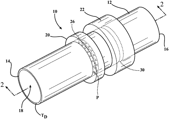
1. A duct, comprising:
a duct body defining an inlet, an outlet, and a channel connecting the inlet and the outlet, the duct body further defining:
an upstream resonator comprising an upstream annular cavity external to the channel and an annular perforated plate coplanar with the upstream annular cavity, the perforated plate defining perforations having perforation necks extending to the upstream annular cavity; and
a downstream resonator comprising a downstream annular cavity external to the channel and an annular opening coplanar with the downstream annular cavity, the annular opening having an annular opening neck extending to the downstream annular cavity, wherein the length of the annular opening neck is greater than the lengths of the perforation necks.
|