| CPC E21D 11/04 (2013.01) [E21D 11/38 (2013.01)] | 4 Claims |

|
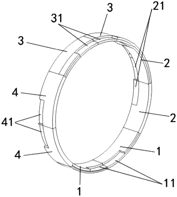
1. A shield tunnel segment structure, comprising segment blocks which are sequentially spliced in a circumferential direction, wherein each segment block forms a closed annular segment structure, and outer diameters of adjacent annular segment structures gradually increase in an axial direction; at least two adjacent segment blocks of the same annular segment structure form an annular inner groove, and at least one segment block of the adjacent annular segment structures is provided with an inner bump which matches the annular inner groove; at least two adjacent segment blocks of the same annular segment structure form an annular outer groove, and at least one segment block of the adjacent annular segment structures is provided with an outer bump which matches the annular outer groove; and the annular outer grooves and the annular inner grooves are staggered in the circumferential direction
wherein each annular inner groove comprises an annular inner front groove and an annular inner rear groove, at least two adjacent segment blocks form the annular inner front groove, at least two adjacent segment blocks form the annular inner rear groove, and the annular inner front grooves and the annular inner rear grooves are staggered in the circumferential direction; and/or
each annular outer groove comprises an annular outer front groove and an annular outer rear groove, at least two adjacent segment blocks form the annular outer front groove, at least two adjacent segment blocks form the annular outer rear groove, and the annular outer front grooves and the annular outer rear grooves are staggered in the circumferential direction;
wherein the segment blocks comprise lower segments, right segments, upper segments and left segments which are sequentially spliced in the circumferential direction; the lower segments comprise at least two lower sub-segments, ends of the at least two lower sub-segments are provided with grooves, and when the two lower sub-segments are spliced, two grooves are connected to form the annular inner front groove;
the right segments comprise at least two right sub-segments, ends of the at least two right sub-segments are provided with grooves, and when the two right sub-segments are spliced, two grooves form the annular inner rear groove;
the upper segments comprise at least two upper sub-segments ends of the at least two upper sub-segments are provided with grooves, and when the two upper sub-segments are spliced, two grooves form the annular outer front groove; and
the left segments comprise at least two left sub-segments, ends of the at least two left sub-segments are provided with grooves, and when the two left sub-segments are spliced, two grooves form the annular outer rear groove.
|