| CPC E05B 15/04 (2013.01) [E05B 47/0012 (2013.01); E05B 2015/0434 (2013.01); E05B 2015/0496 (2013.01)] | 6 Claims |

|
1. An automatically resettable passive swing bolt lock, consisting of a lock body and a key, the key being configured to be inserted into a locking hole of the lock body;
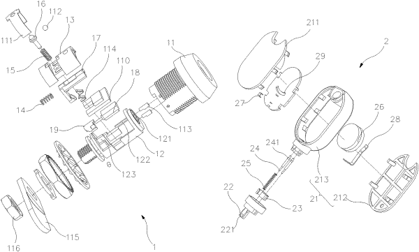
the lock body comprising a lock housing, a rotary compartment, a lock cover, a reset spring, a pin spring, a pin, a lock body PCB, a motor, a cam, a reset pusher block, and two locking contacts; the lock cover being buckled on the rotary compartment, a rotary compartment internal cavity being formed between the lock cover and the rotary compartment, the rotary compartment with the lock cover being rotatably fitted in the lock housing, an outer end of the rotary compartment being provided with two conductive holes; the cam being fixedly sleeved on an output shaft of the motor, the motor being fixedly fitted in the rotary compartment internal cavity, the two locking contacts being movably fitted in the two conductive holes of the rotary compartment, outer ends of the locking contacts facing a key hole of the lock housing, inner ends of the locking contacts being electrically connected to the motor, the reset pusher block being movably fitted in the rotary compartment internal cavity to be moved back and forth in a longitudinal direction, an outer end face of the reset pusher block facing the key hole of the lock housing, an inner end of the reset pusher block being movably fitted with the cam, the reset spring being disposed between the reset pusher block and a wall of the rotary compartment internal cavity, an upper portion of the pin being movably fitted on the lock cover along a lateral direction, a lower end of the pin abutting against the cam, the pin spring being sleeved on the pin, two ends of the pin spring leaning against the lock cover and the cam, respectively; the lock body PCB being installed in the rotary compartment internal cavity, the lock body PCB being electrically connected to the motor and the locking contacts.
|