| CPC B62D 33/0207 (2013.01) [B60R 9/06 (2013.01)] | 20 Claims |

|
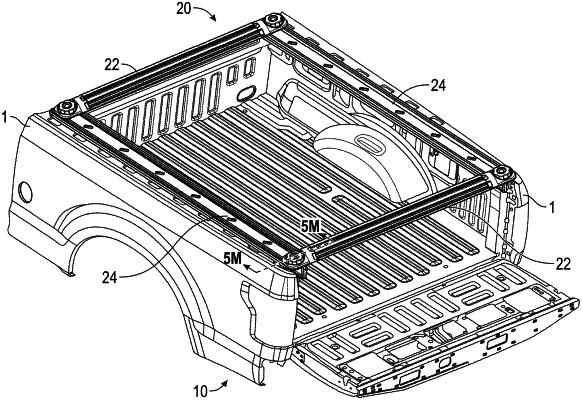
1. A rack assembly configured to be mounted to sidewalls of a truck bed of a vehicle, the rack assembly comprising:
a first side rail configured to be secured to a first sidewall of the truck bed, the first side rail comprising:
a first end, a second end, and a length extending between the first and second ends;
a first flange configured to be positioned above a top surface of the first sidewall when the first side rail is secured to the first sidewall; and
a second flange extending substantially perpendicular relative to the first flange and configured to extend towards a bed surface of the truck bed when the first side rail is secured to the first sidewall, wherein the second flange comprises a channel extending along the length of the first side rail, the channel comprising an opening that faces at least partially toward an interior surface of the first sidewall;
a first clamp mount configured to secure the first side rail to the first sidewall of the truck bed, the first clamp mount comprising:
a first clamp portion configured to engage at least one of an underside of a top portion of the first sidewall and a lip of the first sidewall when the first clamp mount is in a clamped state;
a second clamp portion configured to engage said interior surface of the first sidewall when the first clamp mount is in said clamped state; and
a third clamp portion configured to be received within the channel of the second flange of the first side rail to secure the first clamp mount to the first side rail, wherein said third clamp portion is moveable along a length of the channel of the second flange when the first clamp mount is in an unclamped state to allow a position of the first clamp mount relative to the first sidewall to be adjusted;
a second side rail configured to be secured to a second sidewall of the truck bed, the second side rail comprising:
a first end, a second end, and a length extending between the first and second ends of the second side rail;
a first flange configured to be positioned above a top surface of the second sidewall when the second side rail is secured to the second sidewall; and
a second flange extending substantially perpendicular relative to the first flange of the second side rail and configured to extend towards the bed surface of the truck bed when the second side rail is secured to the second sidewall, wherein the second flange of the second side rail comprises a channel extending along the length of the second side rail, the channel comprising an opening that faces at least partially toward an interior surface of the second sidewall;
a second clamp mount configured to secure the second side rail to the second sidewall of the truck bed, the second clamp mount comprising:
a first clamp portion configured to engage at least one of an underside of a top portion of the second sidewall and a lip of the second sidewall when the second clamp mount is in a clamped state;
a second clamp portion configured to engage said interior surface of the second sidewall when the second clamp mount is in said clamped state; and
a third clamp portion configured to be received within the channel of the second flange of the second side rail to secure the second clamp mount to the second side rail, wherein said third clamp portion is moveable along a length of the channel of the second flange of the second side rail when the second clamp mount is in an unclamped state to allow a position of the second clamp mount relative to the second sidewall to be adjusted; and
at least one cross rail configured to extend across the truck bed of the vehicle, the at least one cross rail comprising:
a first end configured to be secured to each of a plurality of mounting stations of the first side rail; and
a second end configured to be secured to each of a plurality of mounting stations of the second side rail.
|