|
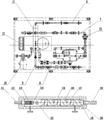
1. A special high-pressure atomization generation device for increasing oil and gas field recovery, comprising an upper framework (3) and a lower framework (5) which are formed by structural steels, wherein the lower framework (5) is provided with an agent pot assembly (2), a gear pump (10), a metering pump (4), an atomization generator (11) and pipelines, the pipelines comprise a low-pressure manifold pipeline (8), a high-pressure liquid inlet pipeline (7), a high-pressure gas inlet pipeline (6) and a high-pressure atomization discharging pipeline (9), a gas outlet pipe (21) is arranged above the agent pot assembly (2), the atomization generator comprises an atomization generator barrel body (117), a gas inlet cap (112), a discharging cap (120), a gas distribution pipe (113), liquid inlet pipes (121), a gas inlet pipe (120) and stirring blocks, two ends of the atomization generator barrel body (117) are respectively provided with a gas inlet cap (112) and a discharging cap (120), the gas inlet cap (112) is provided with a gas inlet pipe (111), the discharging cap (120) is provided with a discharging pipe (119), rotatable stirring blocks are arranged inside the atomization generator barrel body (117), an end of the atomization generator barrel body (117) provided with the gas inlet cap (112) is provided with liquid inlet pipes (121), the gear pump (10) is connected with the agent pot assembly (2) through an agent pot liquid inlet pipe (22), a metering pump (4) is arranged between the agent pot assembly (2) and the atomization generator (11) which are connected through the low-pressure manifold pipeline (7) and the high-pressure liquid inlet pipeline (8), the low-pressure manifold pipeline (7) is connected with the liquid inlet pipes (121), the liquid inlet pipes (121) are connected with the metering pump (4), the gas inlet pipe (111) is connected with an external high-pressure gas source through the high-pressure gas inlet pipeline (6), the discharging pipe (119) is connected with the high-pressure atomization discharging pipeline (9), and a tail end of the high-pressure atomization discharging pipeline (9) is provided with a sprayer using a fan-shaped spraying nozzle.
|
