|
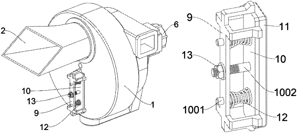
1. A straw crushing device capable of driving a sharpening structure, comprising a main housing (1), wherein the main housing (1) is internally provided with a crushing chamber (101) and a suction chamber (103), a feeding nozzle (2) is installed outside the main housing (1), and the feeding nozzle (2) communicates with a feeding end of the crushing chamber (101); a spline transmission shaft (3) is installed inside the main housing (1), and penetrates through the crushing chamber (101) and the suction chamber (103); a driving motor (6) is installed outside the main housing (1), and is connected to the spline transmission shaft (3); a Y-shaped tool rest (4) is installed on the spline transmission shaft (3), and is located in the crushing chamber (101); a crushing blade (5) is installed on the Y-shaped tool rest (4), and is attached to an inner wall of the crushing chamber (101); an impeller (8) is installed on the spline transmission shaft (3), and is located in the suction chamber (103); a guide frame (9) is installed on an outer side of the main housing (1), and a movable assembly plate (10) is installed inside the guide frame (9); a sharpening stone (11) is installed on one side of the movable assembly plate (10), and an edge of the sharpening stone (11) is chamfered; an adjusting nut (13) is installed on the movable assembly plate (10); an outer side of the crushing chamber (101) is provided with a movable opening (1011), and the guide frame (9) is located at the movable opening (1011); three slide holes (901) are arranged in the guide frame (9) in a line, and two guide slide bars (1001) are arranged on one side of the movable assembly plate (10); the guide slide bars (1001) are slidably connected into the sliding holes (901), and the sharpening stone (11) slides in the movable opening (1011); one side of the movable assembly plate (10) is provided with a screw (1002), the screw (1002) penetrates through the slide hole (901), and the screw (1002) is sleeved with a spring B (12); one end of the spring B (12) is in contact with the movable assembly plate (10), and the other end of the spring B (12) is in contact with an inner side of the guide frame (9); the adjusting nut (13) is threaded to the external of the screw (1002), and the adjusting nut (13) is in contact with an outer side of the guide frame (9); the center of the Y-shaped tool rest (4) is provided with a spline movable hole (401), and the Y-shaped tool rest (4) is slidingly connected to the spline transmission shaft (3) by means of the spline movable hole (401); and the spline transmission shaft (3) is sleeved with a spring A (7), the spring A (7) is located in the crushing chamber (101), one end of the spring A (7) is in contact with the Y-shaped tool rest (4), and the other end of the spring A (7) is in contact with the spline transmission shaft (3).
|
