| CPC H05K 7/20327 (2013.01) [H05K 7/20318 (2013.01); H05K 7/20818 (2013.01); H05K 7/20836 (2013.01)] | 10 Claims |

|
1. A two-phase flow active and passive multi-level data center cabinet cooling device, wherein
in the cooling device, comprising
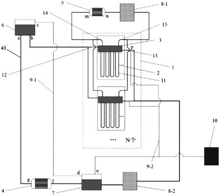
a data center cabinet array (1) comprises a plurality of data center cabinets (2),
each data center cabinet (2) comprises a plurality of blade server motherboards (17), and a rack-level loop thermosiphon (11) of each blade server motherboard (17) is cascaded and connected to a thermosiphon cooling medium inlet pipeline (12) and a thermosiphon cooling medium outlet pipeline (13);
the thermosiphon cooling medium inlet pipeline (12) and the thermosiphon cooling medium outlet pipeline (13) of each data center cabinet are cascaded and connected with other components through a liquid pipeline;
a condensate inlet pipeline (14) and a condensate outlet pipeline (15) of a cabinet condensing unit (3) located on each rack-level loop thermosiphon (11) are cascaded;
both a liquid reservoir (6) of cooling medium inlet and a liquid reservoir (7) of a cooling medium outlet have a first gas space, and are interconnected via a first gas manifold (9-1) between the liquid reservoirs; and a second gas manifold (9-2) of the data center cabinet is connected to a gas chamber (10) with a second gas space and a top of the rack-level loop thermosiphon (11);
the liquid reservoir (6) of the cooling medium inlet is located at a higher position than the rack-level loop thermosiphon (11), while the liquid reservoir (7) of the cooling medium outlet is located at a lower position than the rack-level loop thermosiphon (11); wherein
a liquid outlet (b) of the liquid reservoir of the cooling medium inlet is connected to the thermosiphon cooling medium inlet pipeline (12) of the data center cabinet (2), the thermosiphon cooling medium outlet pipeline (13) connects a cooling medium circulating waste heat recovery device (8-2) and the liquid reservoir (7) of the cooling medium outlet via the liquid pipeline, and is connected to a liquid inlet (f) of a liquid pump circulating a cooling medium, and a liquid outlet (g) of the liquid pump circulating the cooling medium is connected to a liquid inlet (a) of the liquid reservoir of the cooling medium inlet via the liquid pipeline;
the condensate outlet pipeline (15) of the cabinet condensing unit (3) connects a condensate circulating waste heat recovery device (8-1) through the liquid pipeline, and then is connected to a liquid inlet (n) of a liquid pump of a condensate system through the liquid pipeline, and a liquid outlet (m) of the liquid pump of the condensate system is connected to the condensate inlet pipeline (14) of the cabinet condensing unit (3);
a gas outlet (c) of the liquid reservoir of the cooling medium inlet is connected to a gas inlet (d) of the liquid reservoir of the cooling medium outlet, and a gas outlet (e) of the liquid reservoir of the cooling medium outlet is connected to the gas chamber (10) and a top pipeline (p) of the rack-level loop thermosiphon.
|