| CPC H02M 3/1582 (2013.01) [H02M 1/08 (2013.01); H02J 50/10 (2016.02); H02J 50/12 (2016.02); H02J 50/80 (2016.02)] | 20 Claims |

|
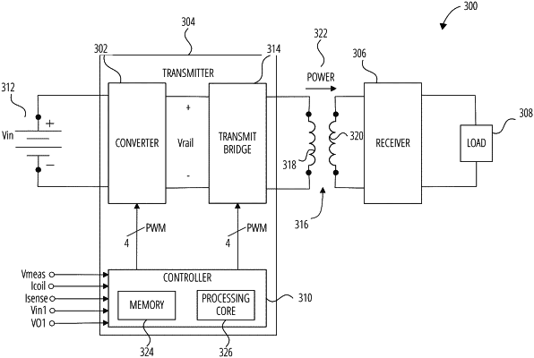
1. An apparatus, comprising:
a converter to convert an input voltage potential to an output voltage potential, the input voltage potential and the output voltage potential including direct current (DC) voltage potentials; and
a controller to:
generate pulse width modulation (PWM) signals responsive to a duty cycle control signal;
control the converter via the PWM signals in a buck mode when the duty cycle control signal is less than a predetermined maximum buck value; and
control the converter via the PWM signals in a cascaded buck-boost mode (CBB mode) when the duty cycle control signal is greater than the predetermined maximum buck value, wherein a duty cycle of at least a portion of the PWM signals transitions linearly with the duty cycle control signal from the buck mode to the CBB mode.
|