| CPC F04B 39/06 (2013.01) [F04B 35/045 (2013.01); F04B 37/18 (2013.01); F04B 39/121 (2013.01); F04B 49/06 (2013.01); F04B 53/06 (2013.01)] | 12 Claims |
|
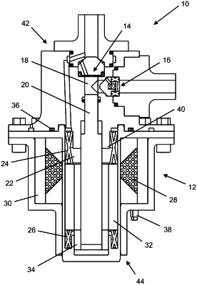
1. A device configured to interact with a working fluid, the device comprising:
a linear motion electromagnet, the linear motion electromagnet including at least one electromagnetic coil, a frame, and an armature within an armature cavity;
a compression cavity;
a piston within a piston cavity, the piston cavity at least partially defining the compression cavity, the armature being attached to at least a portion of the piston;
an inlet valve and a discharge valve, each of the inlet valve and the discharge valve being in fluid communication with the compression cavity;
at least one spring within the armature cavity;
a secondary flow circuit, the secondary flow circuit being configured to isolate the at least one electromagnetic coil from the working fluid; and
a control unit, the control unit being in electrical communication with the at least one electromagnetic coil, the control unit including a control circuit having:
a first major current flow path being configured to charge the at least one electromagnetic coil;
a second major current flow path, the second major current flow path being a low-resistance circuit configured to retain a residual charge within the at least one electromagnetic coil; and
a third major current flow path, the third major current flow path being a high-resistance circuit configured to dissipate the residual charge from the at least one electromagnetic coil,
the control unit further including:
a voltage supply with a voltage supply switch;
a ground with a ground switch;
a coasting switch; and
a retraction switch,
the ground switch and the voltage supply switch being closed with the coasting switch and the retraction switch being open when a current is flowing through the first major current flow path;
the ground switch, the voltage supply switch, and the retraction switch being open and the coasting switch being closed when the current is flowing through the second major current flow path; and
the retraction switch being closed and the ground switch, the voltage supply switch, and the coasting switch being open when the piston is retracting when the current is flowing through the third major current flow path.
|