| CPC B65G 47/901 (2013.01) [B65G 1/04 (2013.01); B65G 59/106 (2013.01); B65G 60/00 (2013.01); B66F 9/186 (2013.01); B65G 2201/0235 (2013.01)] | 4 Claims |
|
1. A raising/lowering conveyance device for a container for conveying an article, comprising:
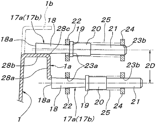
at least two sets of container support means horizontally movable closer to and away from the container and movable up and down with respect to the container, the container support means having a pin holder shaped structure having a large number of container support pins being capable of horizontally protruding and retracting on a side where the container is located and being biased and held at positions protruding from front surface members of the container support means;
the container support means being configured such that the container support pins are operable to enter below a downward step surface of an overhanging rib formed outside the container by approaching movement with respect to the container such that the container can be lifted;
the container support means includes front through holes and the container support pins each include a pin main body passing through an associated one of the front through holes of the container support means and protruding from the container support means, and the pin main bodies each include a flat tip surface perpendicular to an axial center and are formed in a reverse-tapered pin shape whose diameter is increased toward the flat tip surface; and
the front through holes through which the pin main bodies pass have a diameter allowing a largest-diameter tip portion of the pin main body of a reverse-tapered pin shape to penetrate, and the container support pins are configured to be swingable within a range of annular spaces between the front through holes and the pin main bodies.
|