| CPC B60P 7/083 (2013.01) [B60P 3/075 (2013.01)] | 19 Claims |

|
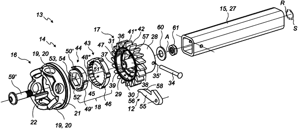
1. A ratchet tie-down tensioner comprising:
a ratchet engagement head that is rotated, when actuated in a tensioning direction and in a return to initial position direction opposite the tensioning direction;
a tie-down engagement head connected to a tie-down winding shaft for rotating said tie-down winding shaft, said tie-down engagement head having a hollow body with inclined teeth on its outer periphery;
a pawl engaged with the outer inclined teeth of the tie-down engagement head in order to allow the tie-down engagement head to rotate in the tensioning direction and prevent the engagement head from rotating in the return to initial position direction; and
a ratchet drive mechanism located between the ratchet engagement and tie-down engagement heads;
wherein the drive mechanism comprises the following two distinct parts:
a self-centering crown floatingly supported in the hollow body of the tie-down engagement head for rotating the tie-down engagement head when the self-centering crown is rotated, said self-centering crown having a toothing on its inner periphery; and
a gear attached to the ratchet engagement head and mounted in the self-centering crown, said gear having a toothing on its outer periphery provided to engage with the inner toothing of the self-centering crown in order to rotate the self-centering crown when the gear rotates in the tensioning direction and to slide over the inner toothing of the self-centering crown without rotating the self-centering crown when the gear rotates in the return to initial position direction;
and wherein:
at least one of the toothings is formed by curved spring blades extending substantially following the periphery on which said toothing is situated, each spring blade having a tooth at its free end provided in order for the toothing of the gear to mesh with the toothing of the self-centering crown.
|