| CPC B60H 1/3457 (2013.01) [B60H 1/00564 (2013.01)] | 15 Claims |

|
1. An air discharge device comprising:
a duct defining a main flow path through which an air flow passes, and a main hole having an opening and configured to discharge the air flow as a working air flow toward a downstream from the main flow path, the opening of the main hole having a flow path height in a minor direction of the opening and a flow path width in a major direction of the opening;
a throttle portion provided in the duct to reduce the flow path height of the main flow path from an upstream of the air flow toward the downstream of the air flow; and
a plurality of partitions arranged to divide the main flow path into a pair of side flow paths located at both sides in the major direction, and at least one center flow path located between the pair of side flow paths, wherein
the plurality of partitions are disposed in the duct, and the flow path width of the center flow path is reduced from the upstream of the air flow toward the downstream of the air flow,
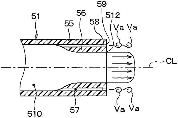
the duct has a duct part made of a double pipe structure including an outer wall portion and an inner wall portion, at a portion connected to the main hole,
the throttle portion is provided in the inner wall portion, and
an upstream end of each of the plurality of partitions is provided at positions separated from the inner wall portion.
|