| CPC H05K 7/20872 (2013.01) [H05K 7/20927 (2013.01)] | 5 Claims |

|
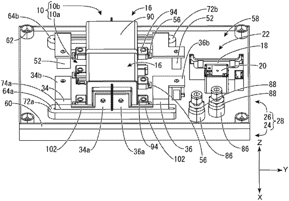
1. A circuit structure comprising:
a heat generating component;
a bus bar connected to a connection portion of the heat generating component;
an insulating base member configured to hold the heat generating component and the bus bar; and
a coolant flow path provided inside the base member and through which a coolant flows,
wherein the bus bar is in thermal contact with the coolant flow path,
the base member includes a passage wall portion constituting the coolant flow path, and the bus bar is brought into thermal contact with the coolant flow path due to a portion of the bus bar being embedded or press-fitted into the passage wall portion, and
the passage wall portion includes a groove through which the coolant flows and a protruding portion that protrudes into the groove, the protruding portion includes a slit-shaped bus bar housing groove that is open in the upper surface thereof that does not face the groove, and the bus bar is press-fitted into the bus bar housing groove.
|