| CPC H05B 45/3725 (2020.01) [H02M 1/32 (2013.01); H02M 3/1582 (2013.01); H05B 45/10 (2020.01); H05B 45/325 (2020.01)] | 20 Claims |

|
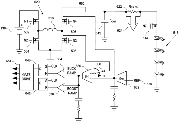
20. A buck-boost driver circuit comprising:
an H-bridge comprising:
a low-side switch that, in a shunting mode, carries a first average current;
a high-side switch that, in a non-shunting mode, carries a second average current; and
an average current mode control circuit that uses an error voltage from a first circuit loop that comprises the low-side switch and uses a load current from a second circuit loop that comprises the high-side switch to adjust the first and second average currents to be substantially the same to reduce a current pulse width of the load current, the low-side switch allowing an output capacitor of the buck-boost driver circuit to operate without a shunt switch; and
a set of comparators that uses the error voltage to determine a duty cycle of at least one or more switches of the H-bridge.
|