| CPC H04N 1/121 (2013.01) [B65H 31/00 (2013.01); G03G 15/607 (2013.01); H04N 1/00554 (2013.01); B65H 2404/63 (2013.01)] | 20 Claims |

|
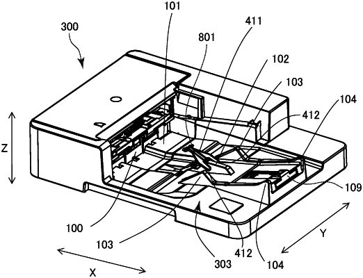
1. A sheet discharging apparatus, comprising:
a discharge unit configured to discharge a sheet in a discharge direction;
a stacking portion on which the sheet discharged by the discharge unit is stacked; and
a swing member configured to swing around a swing shaft,
wherein the stacking portion includes
a first portion including a first surface that is provided on an upper portion of the first portion and is inclined upward toward a downstream side in the discharge direction, the first portion being configured to support the sheet at the first surface,
a second portion arranged separately from the first portion in a sheet width direction orthogonal to the discharge direction, the second portion including a second surface that is provided on an upper portion of the second portion and is inclined upward toward the downstream side in the discharge direction, the second portion being configured to support the sheet at the second surface,
a bottom surface portion arranged between the first portion and the second portion in the sheet width direction, the bottom surface portion being lower than both the first surface and the second surface,
a moving member configured to be moved in the discharge direction with respect to the first portion and the second portion and to support the sheet discharged by the discharge unit, the moving member being arranged between the first portion and the second portion in the sheet width direction, the moving member being movable to a position downstream of the first surface and the second surface in the discharge direction,
wherein the swing shaft is positioned above the first surface and the second surface,
wherein the swing member is configured to be at a position where the swing member overlaps both the first portion and the second portion when viewed in the sheet width direction in a case where the swing member is not in contact with the sheet discharged by the discharge unit, and is configured to be moved from the position in a case where the swing member is pushed by the sheet discharged by the discharge unit, and
wherein the swing member is arranged such that a lower end of the swing member remains separated from the bottom surface portion of the stacking portion.
|