| CPC H03L 7/0992 (2013.01) [H03L 7/093 (2013.01); H03L 7/0995 (2013.01); H03M 1/1014 (2013.01)] | 20 Claims |

|
8. A digital phase-locked loop circuit comprising:
a time-to-digital converter for generating a loop filter input signal, the digital phase-locked loop circuit comprising:
the time-to-digital converter configured to generate the loop filter input signal by receiving a phase-locked loop input clock and a feedback clock,
a loop filter configured to generate an output signal by receiving the loop filter input signal,
an oscillator configured to generate an oscillation clock by receiving the output signal, and
a divider configured to generates the feedback clock that divides a frequency of the oscillation clock by receiving the oscillation clock, wherein the time-to-digital converter comprises
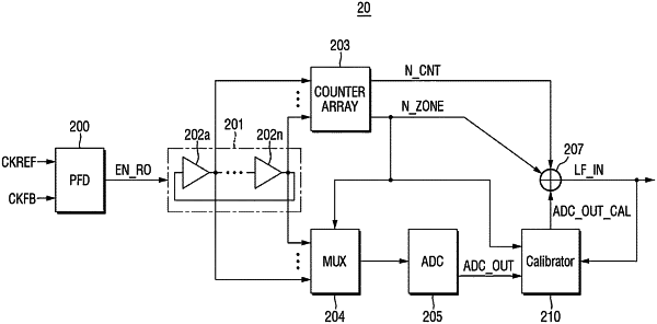
a phase frequency detector configured to receive the phase-locked loop input clock and the feedback clock and output an enable signal during a first pulse width in which a phase error occurs between the phase-locked loop input clock and the feedback clock,
a ring oscillator configured to be turned on based on the enable signal and configured to perform oscillation with multi-phase clocks of a first period,
a counter array configured to count a number of oscillations in which the ring oscillator oscillates in the first period by the number of positive integers during the first pulse width,
a multiplexer configured to divide the first period into a plurality of zones using edge information of the multi-phase clocks of the ring oscillator, and selects and outputs voltage information of a plurality of neighboring phase clocks included in a first zone from the plurality of zones,
an analog digital converter configured to generate an analog-to-digital conversion output by receiving the voltage information included in the first zone as an input,
a calibrator configured to receive the analog-to-digital conversion output and the loop filter input signal and generate a calibrated analog-to-digital conversion output by calibrating the analog-to-digital conversion output; and
a first adder configured to output the loop filter input signal by receiving the first zone, the number of oscillations, and the calibrated analog-to-digital conversion output, and
wherein the calibrator comprises,
an offset lookup table generation circuit configured to receive the loop filter input signal and generate a plurality of offset lookup tables that offset an error between an ideal digital code value and a nonlinear digital code value over time of the loop filter input signal,
a gain-corrected analog-to-digital conversion output generator circuit configured to generate a gain-corrected analog-to-digital conversion output that offsets a difference between a first gain having the ideal digital code value and a second gain with the nonlinear digital code value, and
a second adder configured to generate the calibrated analog-to-digital conversion output by adding the offset lookup table and the gain-corrected analog-to-digital conversion output.
|