| CPC H03K 21/10 (2013.01) [H03K 5/1565 (2013.01); H03K 21/026 (2013.01)] | 6 Claims |

|
1. An apparatus comprising:
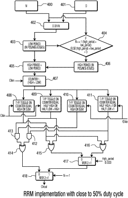
a Rational Ratio Multiplier (RRM) implementation comprising:
a first input to receive a first value N;
a second input to receive a second value D, wherein the value N and the value D provide a rational ratio fraction N/D while D>N of the RRM;
a counter, the counter configured to count from 1 to a sum of a high period value and a low period value, wherein the high period value is defined by a desired number of rising edges and falling edges of an input clock while an output clock is at a high clock period and the low period value is defined by a desired number of rising edges and falling edges of the input clock while the output clock is at a low clock period, wherein the low period value and the high period value are derived from the N value and the D value;
a first T-FF that samples at a rising edge of the input clock;
a second T-FF that samples at the rising edge of the input clock;
a third T-FF that samples at a falling edge of the input clock;
a fourth T-FF that samples at the falling edge of the input clock;
wherein the first T-FF, the second T-FF, the third T-FF, and the fourth T-FF are configured to toggle based a count of the counter;
a logic circuit configured to receive output signals of the first T-FF, the second T-FF, the third T-FF, and the fourth T-FF and generate from the output signals the output clock.
|