| CPC H03K 17/302 (2013.01) [H01L 27/0629 (2013.01); H03K 2017/307 (2013.01)] | 17 Claims |
|
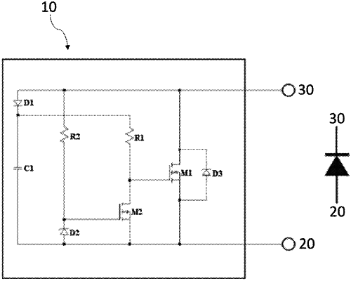
1. A field-effect transistor (FET) based synchronous rectifier, comprising:
a first terminal and a second terminal;
a first EFT (M1) and a second FET (M2),
wherein the second FET (M2) is adapted to control operation of the first FET (M1) to thereby allow unidirectional current flow when the two terminals are connected with an external circuit;
wherein the FET based synchronous rectifier comprises a fully integrated single-chip device adapted to emulate a diode;
wherein the first FET (M1) has at least a first gate electrode, a first source electrode and a first drain electrode; the second FET (M2) has at least a second gate electrode, a second source electrode and a second drain electrode; the second drain electrode of the second FET (M2) is in series connection with the first gate electrode of the first FET (M1);
a first diode (D1) and a first resistor (R1) connected in series between the second drain electrode of the second FET (M2) and the second terminal; and
a first capacitor (C1) connected in series between the first diode (D1) and the second source electrode of the second FET (M2),
the FET based synchronous rectifier further comprises a second resistor (R2) and a second diode (D2) connected in parallel with the first capacitor (C1) and the first diode (D1) in between the first terminal and the second terminal,
wherein the second resistor (R2) is in series connection with the second gate electrode of the second FET (M2),
wherein the second resistor (R2) is directly connected to the second terminal, and the second diode (D2) is directly connected to the first terminal.
|