| CPC H03F 1/0233 (2013.01) [H03F 3/245 (2013.01); H04B 1/40 (2013.01); H03F 2200/105 (2013.01); H03F 2200/451 (2013.01)] | 17 Claims |

|
1. A transmission circuit comprising:
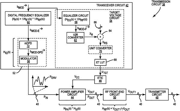
a power amplifier circuit coupled to a transmitter circuit via a radio frequency (RF) front-end circuit and configured to amplify an RF signal based on a modulated voltage and provide the amplified RF signal to the RF front-end circuit;
an envelope tracking (ET) integrated circuit (ETIC) configured to generate the modulated voltage based on a modulated target voltage; and
a transceiver circuit configured to:
generate the RF signal from a time-variant modulation vector;
generate the modulated target voltage as a function of the time-variant modulation vector; and
apply at least one complex filter to at least the RF signal to compensate for a voltage distortion filter created on an output stage of the power amplifier circuit by coupling the power amplifier circuit with the RF front-end circuit across a modulation bandwidth.
|