| CPC H02P 21/34 (2016.02) [H02P 21/10 (2013.01); H02P 2207/055 (2013.01)] | 19 Claims |

|
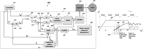
16. A permanent magnet synchronous motor (PMSM) system with field oriented control (FOC), the PMSM system comprising:
a PMSM motor;
an inverter coupled to the PMSM motor; and
a controller coupled to the inverter, wherein the controller is configured to start the PMSM by:
setting a control loop of the PMSM in open-loop mode;
while the control loop is in open-loop mode:
setting a first direction for a first current component of the PMSM, wherein the PMSM has a second current component perpendicular to the first current component, wherein the first current component and the second current component are in a two-axis coordinate system that is rotating with a rotor of the PMSM, wherein the first current component and the second current component are related to three-phase currents supplied to windings of a stator of the PMSM through a Clarke transformation and a Park transformation;
positioning the rotor of the PMSM along the first direction;
after positioning the rotor, abruptly setting a second direction for the first current component, wherein the second direction is perpendicular to the first direction; and
after abruptly setting the second direction, asynchronously driving the rotor to rotate the rotor, wherein asynchronously driving the rotor comprises, providing, by a controller of the PMSM, a transformation angle for the Park transformation, wherein the transformation angle is independent of an angle of the rotor, wherein a value of the transformation angle provided by the controller changes from a first pre-determined value to a second pre-determined value;
after asynchronously driving the rotor for a first period of time, operating the control loop in a first closed-loop mode; and
after operating the control loop in the first closed-loop mode for a second period of time, operating the control loop in a second closed-loop mode different from the first closed-loop mode, wherein the control loop is driven by a first error signal and a second error signal, wherein the first error signal is computed by subtracting the first current component from a first reference current value, wherein the first reference current value has a first constant value during the asynchronously driving and during the first closed-loop mode, and has a timing-varying value during the second closed-loop mode.
|