| CPC H02M 7/539 (2013.01) [H02M 1/0025 (2021.05); H02M 7/48 (2013.01)] | 2 Claims |

|
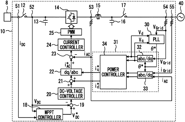
1. A power conversion device comprising:
a power conversion circuit connected to a direct-current power supply and a power system and configured to perform conversion between direct-current power and alternating-current power;
a phase-locked loop circuit configured to output a phase instruction value based on a system alternating-current voltage phase of the power system; and
a control circuit configured to control the power conversion circuit based on the phase instruction value from the phase-locked loop circuit,
the phase-locked loop circuit including:
a phase difference calculation section configured to calculate a phase difference in a predetermined cycle, the phase difference representing a deviation of the phase instruction value from the system alternating-current voltage phase of the power system;
a phase difference correction section configured to, if a difference between a current phase difference currently calculated by the phase difference calculation section and a previous phase difference previously calculated by the phase difference calculation section exceeds a predetermined reference, add a first correction amount to the current phase difference to output the corrected current phase difference, and if the difference does not exceed the reference, output the uncorrected current phase difference without adding the first correction amount to the current phase difference; and
a phase instruction value generation section configured to output the phase instruction value based on the output of the phase difference correction section.
|