| CPC H02M 3/158 (2013.01) [G09G 3/006 (2013.01); H02M 3/1584 (2013.01); G09G 2330/12 (2013.01); H02M 3/00 (2013.01); H02M 3/1582 (2013.01); H02M 5/00 (2013.01); H02M 7/00 (2013.01)] | 16 Claims |

|
1. A voltage conversion circuit, comprising:
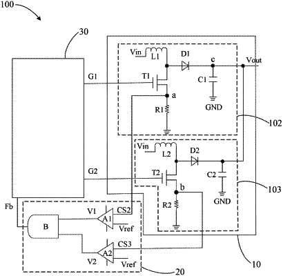
a voltage conversion module receiving an input voltage, wherein the voltage conversion module comprises at least two voltage conversion units, and the voltage conversion module is configured to convert the input voltage into a target voltage;
a comparison module electrically connected to the voltage conversion module, wherein the comparison module receives a reference voltage, and the comparison module acquires a testing voltage of each of the voltage conversion units, and compares each of the testing voltages with the reference voltage to generate a feedback signal; and
a control module electrically connected to the voltage conversion module and the comparison module, wherein the control module receives the feedback signal and controls the voltage conversion module to convert the input voltage to the target voltage based on the feedback signal;
wherein the voltage conversion circuit comprises a first voltage conversion unit and a second voltage conversion unit;
wherein the comparison module acquires a first testing voltage of the first voltage conversion unit and a second testing voltage of the second voltage conversion unit, and compares the first testing voltage and the second testing voltage with the reference voltage respectively to generate the feedback signal;
wherein the control module receives the feedback signal, outputs a first control signal to the first voltage conversion unit and outputs a second control signal to the second voltage conversion unit based on the feedback signal for controlling the first voltage conversion unit and the second voltage conversion unit to convert the input voltage to the target voltage;
wherein the first voltage conversion unit comprises a first transistor, a first inductor, a first capacitor, a first diode and a first resistor, the second voltage conversion unit comprises a second transistor, a second inductor, a second capacitor, a second diode and a second resistor;
wherein a gate of the first transistor receives the first control signal, a source of the first transistor, a first end of the first inductor, and an anode of the first diode are electrically connected, a drain of the first transistor and a first end of the first resistor are electrically connected to a first testing voltage output terminal, the first testing voltage output terminal is configured for outputting the first testing voltage, a second end of the first inductor receives the input voltage, a second end of the first resistor and a first end of the first capacitor are connected to a grounding end, and a cathode of the first diode and a second end of the first capacitor are connected to a target voltage output terminal;
wherein a gate of the second transistor receives the second control signal, a source of the second transistor, a first end of the second inductor, and an anode of the second diode are electrically connected, a drain of the second transistor and a first end of the second resistor are electrically connected to a second testing voltage output terminal, the second testing voltage output terminal is configured for outputting the second testing voltage, a second end of the second inductor receives the input voltage, a second end of the second resistor and a first end of the second capacitor are connected to the grounding end, and a cathode of the second diode and a second end of the second capacitor are connected to the target voltage output terminal.
|