| CPC H02K 15/03 (2013.01) [H01F 13/003 (2013.01); H02K 1/16 (2013.01); H02K 1/2713 (2013.01); H02K 7/003 (2013.01); H02K 5/00 (2013.01)] | 6 Claims |

|
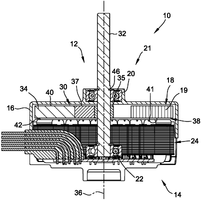
1. An axial flux rotor, for use in an axial flux motor, said axial flux rotor prepared by a process comprising the steps of:
stamping a plurality of laminations, each of said plurality of laminations including opposed parallel first and second external planar faces and opposed first and second ends;
overlying one of the opposed parallel external planar faces of one of the plurality of laminations over another of the opposed parallel external planar faces of another of the plurality of laminations;
overlying other of the opposed parallel external planar faces of one of the plurality of laminations over one of the opposed parallel external planar faces of another of the plurality of laminations to provide a first rotor pole;
repeating the stamping and overlying one and overlying other of the opposed parallel external planar faces to provide at least one additional rotor pole, thereby providing a plurality of rotor poles;
positioning the plurality of rotor poles in a spaced apart relationship, around a rotor center of rotation with the opposed first and second ends of the laminations tangentially oriented with respect to the rotor center of rotation;
providing a plurality of magnetizable permanent magnets, each one of the magnetizable permanent magnets having a longitudinal axis thereof; and
positioning each of the magnetizable permanent magnets between adjacent rotor poles with the longitudinal axis positioned in a radial direction relative to the rotor center of rotation and so defining radially inward surface and an opposed radially outward surface, the magnetizable permanent magnet having a first face adjacent the first external planar face of the rotor and having a second face adjacent the second external planar face of the rotor; and
overmolding the plurality of rotor poles with a moldable material after positioning each of the magnetizable permanent magnets between adjacent rotor poles.
|