| CPC H02K 1/165 (2013.01) [B60K 1/00 (2013.01); H02K 1/276 (2013.01); H02K 7/006 (2013.01); H02K 21/14 (2013.01); H02K 2201/03 (2013.01)] | 20 Claims |
|
1. An electric machine comprising:
a housing;
a rotor assembly rotatably attached to the housing, the rotor assembly including a rotor core and a magnet mounted to the rotor core; and
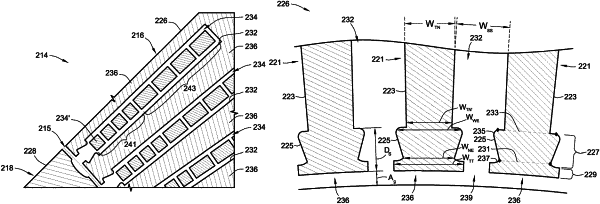
a stator assembly coaxial with and separated by an airgap from the rotor assembly, the stator assembly including a stator core defining a plurality of circumferentially spaced stator slots, a plurality of radially aligned stator teeth separating the stator slots, and a plurality of electromagnetic windings located in the stator slots, each of the stator teeth having an elongated tooth body with a tooth head at a radial end of the tooth body, the tooth head having an axial cross-section with a trapezoidal crown integral with a rectangular tip, the trapezoidal crown having an isosceles trapezium shape with a narrow edge, a wide edge parallel to and wider than the narrow edge, and a pair of angled edges oblique with and connecting the wide and narrow edges, the narrow edge of the trapezoidal crown facing the airgap.
|