| CPC H02K 16/04 (2013.01) [H01R 39/04 (2013.01); H02K 1/2793 (2013.01); H02K 3/26 (2013.01); H02K 11/044 (2013.01); H02K 13/006 (2013.01); H02K 16/00 (2013.01); H02K 21/24 (2013.01); H02K 23/54 (2013.01); H02K 47/14 (2013.01); H02P 31/00 (2013.01); H02K 53/00 (2013.01); Y10S 74/09 (2013.01)] | 12 Claims |

|
1. An electric motor-generator comprising:
a motor-generator shaft having a shaft axis;
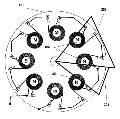
a plurality of field coils generally evenly spaced about a periphery of a stator, one or more of the field coils wound about an axis generally parallel to the shaft axis, wherein axes of respective field coils are generally radially and equidistantly spaced from the shaft axis;
a plurality of permanent magnets generally evenly spaced about a periphery of each of a pair of rotors, one or more of the magnets disposed along an axis of poles generally parallel to the shaft axis, wherein axes of respective magnets are generally radially and equidistantly spaced from the shaft axis on respective rotors by generally the same radius as the field coils are from the shaft axis, the pair of rotors disposed one on each side of the stator;
such that during rotation of the rotors, a center, of each magnet generally passes across a center of each coil;
the magnets arrayed on respective rotors in alternate pole orientation N-S S-N, the magnets of one rotor offset from the magnets of the other rotor by one pole orientation, such that as a N pole on the one rotor is passing directly across one end of a field coil, a S pole of a corresponding magnet on the other rotor is passing directly across the other end of the field coil;
the motor-generator further comprising:
a field coil power supply;
a rotary electrical switch consisting of commutator with brushes;
wherein the rotary switch enables paired alternating periods of current flow and no current flow into respective stator field coils, such that in a period pair the period of current flow is shorter than the period of no current flow;
a series of high capacity capacitors wired in parallel with the field coil power supply such that the capacitors alternately discharge into the field coils when the field coils are switched ‘on’ in a motor mode, and the capacitors are charged by power from the field coils when the field coils are switched ‘off’ and are operating in a generator mode.
|