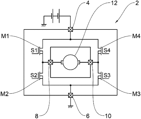
| CPC H02H 7/0838 (2013.01) [H02P 7/04 (2016.02); H02P 29/028 (2013.01)] | 15 Claims |

|
1. A device for supplying power to an inductive load, the device comprising:
an H-bridge switching structure coupled to a positive power supply and an electrical ground, the H-bridge switching structure comprising a first switch, a second switch, a third switch, and a fourth switch that are distributed over two branches of the H-bridge, the switching structure being configured to drive a current in the inductive load through a first control output and a second control output; and
an anomaly detector configured to generate at least one item of anomaly detection information about detection of an anomaly at the H-bridge switching structure, the anomaly detector comprising:
a first voltage generator controlled and configured to deliver a first reference voltage,
a second voltage generator controlled and configured to deliver a second reference voltage, said first and second voltage generators being coupled respectively to the first control output and the second control output, the value of the first reference voltage being greater than the value of the second reference voltage,
a first current measuring device configured to measure a current at the output of the first voltage generator,
a second current measuring device configured to measure a current at an output of the second voltage generator,
a third current measuring device coupled between the first switch and the first control output,
a fourth current measuring device coupled between the second switch and the first control output,
a fifth current measuring device coupled between the third switch and the second control output,
a sixth current measuring device coupled between the fourth switch and the second control output,
the current measuring devices being configured to respectively measure the currents flowing through said switches,
a seventh voltage measuring device coupled to the first control output, and
an eighth voltage measuring device coupled to the second control output,
said seventh and eighth voltage measuring devices being configured to measure voltages on the control outputs.
|