| CPC H01R 31/08 (2013.01) [H01R 4/28 (2013.01); H01R 13/42 (2013.01); H01R 13/629 (2013.01)] | 4 Claims |

|
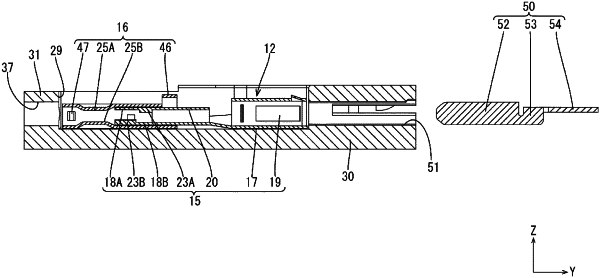
1. A joint connector for connecting a plurality of wires, comprising:
a lower housing;
an upper cover assembled with the lower housing;
a plurality of terminals respectively connected to front end parts in an extending direction of the plurality of wires; and
a busbar connected to the plurality of terminals,
wherein:
the busbar disposed in the lower housing includes a plurality of tabs,
each of the plurality of terminals disposed in the lower housing includes a tube portion, each of the plurality of tabs being inserted into the tube portion, a sandwiching portion extending along the extending direction and configured to sandwich one of the plurality of wires, and a sliding portion disposed outside the sandwiching portion, movable along the extending direction and including a pressurizing portion configured to pressurize the sandwiching portion toward the wire with the one of the plurality of wires sandwiched by the sandwiching portion, and
a terminal holding portion projecting downward from the upper cover is engaged with the terminals.
|