| CPC H01R 13/6582 (2013.01) [H01R 13/405 (2013.01); H01R 13/502 (2013.01); H01R 13/516 (2013.01); H01R 13/6477 (2013.01); H01R 2201/26 (2013.01)] | 20 Claims |

|
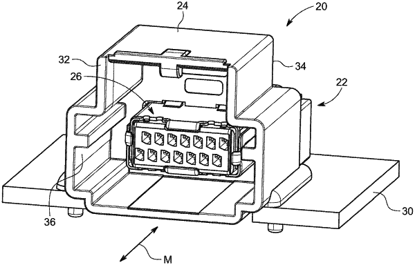
1. An electrical connector comprising:
a set of upper conductive signal terminals aligned in a upper row and a set of lower conductive signal terminals aligned in a lower row, each signal terminal including a mating interface section configured to mate with another electrical connector, an intermediate section extending from a rear end of the mating interface section, and a tail section extending from a rear end of the intermediate section and configured to mate with another component;
an upper insulative housing surrounding the intermediate sections of the upper signal terminals, the mating interface sections of the upper signal terminals extending rearwardly from the upper housing and the tail sections of the upper signal terminals extending forwardly from the upper housing;
a lower insulative housing surrounding the intermediate sections of the lower signal terminals, the mating interface sections of the lower signal terminals extending rearwardly from the lower housing and the tail sections of the lower signal terminals extending forwardly from the lower housing;
first and second insulative inserts partially surrounding the tail sections of the upper signal terminals and partially surrounding the tail sections of the lower signal terminals, the first insert being separately formed from the upper housing and from the second insert, and the second insert being separately formed from the lower housing and from the first insert,
wherein the first and second inserts form a set of upper spaced apart passageways aligned in an upper row, the tail sections of the upper signal terminals extending through and outwardly from the upper passageways, and wherein the first and second inserts form a set of spaced apart lower passageways aligned in a lower row, the tail sections of the lower signal terminals extending through and outwardly from the lower passageways; and
a conductive shield partially surrounding the housings and the inserts.
|