| CPC H01H 33/66207 (2013.01) [H01H 33/56 (2013.01); H01H 33/66238 (2013.01); H01H 33/666 (2013.01); H01H 2033/66223 (2013.01)] | 4 Claims |

|
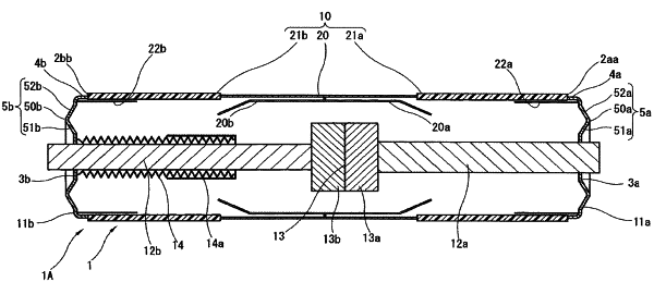
1. A vacuum interrupter comprising:
a vacuum container including an insulating cylindrical body, the vacuum container being sealed with a fixed-side flange on a fixed side thereof which is one end side in an axial direction of the cylindrical body, and being sealed with a movable-side flange on a movable side thereof which is an other end side in the axial direction;
a fixed-side energizing shaft extending in a vacuum container inner side direction of the axial direction, in a fixed-side flange middle portion;
a fixed electrode supported on an end portion on an extending direction side of the fixed-side energizing shaft;
a movable-side energizing shaft which extends in the axial direction while passing through a movable-side flange middle portion in the axial direction, and is supported on a vacuum container inner side of the movable-side flange via a bellows which is extensible in the axial direction, so as to be movable in the axial direction; and
a movable electrode which is supported on an end portion on the vacuum container inner side of the movable-side energizing shaft so as to face the fixed electrode, and comes in contact with and separates from the fixed electrode in accordance with a movement of the movable-side energizing shaft,
wherein the fixed-side flange is formed with an annular expansion portion between the flange middle portion and a flange outer peripheral edge portion of the fixed-side flange and the movable-side flange is formed with an annular expansion portion between the flange middle portion and a flange outer peripheral edge portion of the movable-side flange, and each of the annular expansion portions is formed in an annular shape extending along an outer periphery of a corresponding one of the flange middle portions, and is formed in a shape expanding in an vacuum container outer side direction of the axial direction, and
wherein each of the expansion portions includes:
an inner peripheral side annular wall which is positioned from a corresponding one of distal end portions in an expanding direction of a corresponding one of the expansion portions toward a corresponding one of the flange middle portions, and has a shape of which a diameter increases as a distance to the corresponding one of the distal end portions decreases; and
an outer peripheral side annular wall which is positioned from a corresponding one of the distal end portions in the expanding direction of a corresponding one of the expansion portions toward a corresponding one of the flange outer peripheral edge portions, and has a shape of which a diameter decreases as a distance to the corresponding one of the distal end portions decreases.
|