| CPC H01F 17/0013 (2013.01) [H01F 27/2804 (2013.01); H01F 27/292 (2013.01); H01F 37/00 (2013.01); H01F 2017/0093 (2013.01)] | 18 Claims |

|
1. A common-mode choke coil comprising:
a multilayer body including a plurality of non-conductor layers, the plurality of non-conductor layers being stacked and each made of a non-conductor, the multilayer body including a first lateral side, a second lateral side, and an end face extending from the first lateral side to the second lateral side;
a first coil and a second coil that are incorporated in the multilayer body, the first coil having a first end and a second end which are different ends of the first coil, the second coil having a third end and a fourth end which are different ends of the second coil, the first coil extending along the first lateral side, then along the end face, and then along the second lateral side, a distance from the first coil to the end face being in a range from 0.025 mm to 0.105 mm;
a first terminal electrode and a second terminal electrode that are provided on an outer surface of the multilayer body, the first terminal electrode being electrically connected to the first end, and the second terminal electrode being electrically connected to the second end; and
a third terminal electrode and a fourth terminal electrode that are provided on an outer surface of the multilayer body, the third terminal electrode being electrically connected to the third end, and the fourth terminal electrode being electrically connected to the fourth end,
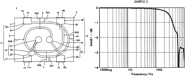
wherein when an Sdd21 transmission characteristic representing a transmission characteristic for a differential-mode component is measured at a frequency of from 0.1 GHz to 100 GHz, the Sdd21 transmission characteristic is less than or equal to −3 dB at a frequency of greater than or equal to 30 GHz,
wherein when an Scc21 transmission characteristic representing a transmission characteristic for a common-mode component is measured at a frequency of from 10 GHz to 60 GHz, the Scc21 transmission characteristic is minimum at a frequency of greater than or equal to GHz, and
wherein the Scc21 transmission characteristic has a minimum value of less than or equal to −20 dB.
|