| CPC G21C 15/26 (2013.01) [G21C 15/12 (2013.01); G21C 15/18 (2013.01)] | 15 Claims |
|
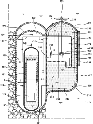
1. A passive cooling system for a nuclear reactor, the passive cooling system comprising:
a first space including an energy release space, the energy release space having a reactor vessel therein, the reactor vessel configured to accommodate a reactor core; and
a cooling space including an energy absorbing space, an energy transfer space, and a coolant spray pipe,
wherein the first space and the cooling space are separated from each other by a first separation wall and the cooling space is defined by the first separation wall and an outer wall, the energy absorbing space configured to accommodate cooling water, the energy absorbing space being separated from the energy release space, the energy absorbing space configured to communicate with the energy release space through a pressure balance pipe such that a pressure in the energy release space is transferred to the energy absorbing space,
wherein the energy transfer space is disposed above the energy absorbing space and isolated from the energy release space and the energy absorbing space, the energy transfer space configured to absorb and cool heat transferred from the reactor vessel through a cooling flow conduit and discharge the absorbed heat through the outer wall defining the cooling space, and
the coolant spray pipe configured to transfer the cooling water accommodated in the energy absorbing space and pressurized by the pressure balance pipe to the energy transfer space,
wherein the cooling flow conduit includes a plurality of heat exchangers, the heat exchangers including,
a first heat exchanger configured to absorb the heat in the reactor vessel, and
a second heat exchanger in a saturated vapor pressure cooling chamber and configured to discharge the heat absorbed by the first heat exchanger,
wherein the energy transfer space includes the saturated vapor pressure cooling chamber and a reference atmospheric pressure chamber,
wherein the saturated vapor pressure cooling chamber is in physical contact with an upper portion of the first separation wall, and configured to accommodate cooling water therein,
wherein the second heat exchanger of the cooling flow conduit and a spray-side end of the coolant spray pipe are located in the saturated vapor pressure cooling member,
wherein the reference atmospheric pressure chamber is disposed under the saturated vapor pressure cooling chamber, separated from the saturated vapor pressure cooling chamber by a second separation wall, and configured to communicate with the saturated vapor pressure cooling chamber at a lower side of the saturated vapor pressure cooling chamber, the reference atmospheric pressure chamber configured to be at least partially filled with air so as to achieve a pressure balance with the cooling water in the saturated vapor pressure cooling chamber, and receive cooling water from the saturated vapor pressure cooling chamber,
wherein the passive cooling system is configured to change a level of the cooling water in the reference atmospheric pressure chamber according to a pressure in the saturated vapor pressure cooling chamber,
wherein the passive cooling system is configured to spray cooling water in the energy absorbing space onto the second heat exchanger through the spray-side end of the coolant spray pipe,
wherein the reference atmospheric pressure chamber is surrounded by the saturated vapor pressure cooling chamber, the energy absorbing space, and the energy release space so as not to be adjacent to the outer wall defining the cooling space,
wherein the reference atmospheric pressure chamber has a closed top structure which separates the reference atmospheric pressure chamber from the saturated vapor pressure cooling chamber, and
wherein the pressure balance pipe has an inverted U shape and is provided such that a top of the inverted U shape is at a higher level than a top of the energy absorbing space.
|