| CPC G11C 11/4096 (2013.01) [G06F 7/5443 (2013.01); G11C 11/4074 (2013.01); G11C 11/4076 (2013.01); G11C 11/4085 (2013.01); G11C 11/4094 (2013.01)] | 54 Claims |

|
1. An in-memory computation circuit, comprising:
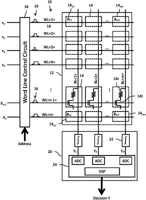
a memory array including a plurality of memory cells arranged in a matrix with plural rows and plural columns, each row including a first word line connected to the memory cells of the row, and each column including a first bit line connected to the memory cells of the column, wherein computational weights for an in-memory compute operation are stored in the memory cells;
a word line control circuit configured to simultaneously actuate the plurality of first word lines in response to input signals providing coefficient data for said in-memory compute operation by applying word line signal pulses to the first word lines; and
a column processing circuit connected to the first bit lines and configured to process analog signals developed on the first bit lines in response to the simultaneous actuation of the plurality of first word lines to generate multiply and accumulate output signals for said in-memory compute operation,
wherein:
the memory array further includes a plurality of reference memory cells connected to a reference word line to receive a reference word line signal pulse and connected to a reference bit line; and
the word line control circuit is further configured to modulate pulse widths of the word line signal pulses in response to an analog reference signal developed on the reference bit line in response to the actuation of the reference word line by the reference word line signal pulse.
|